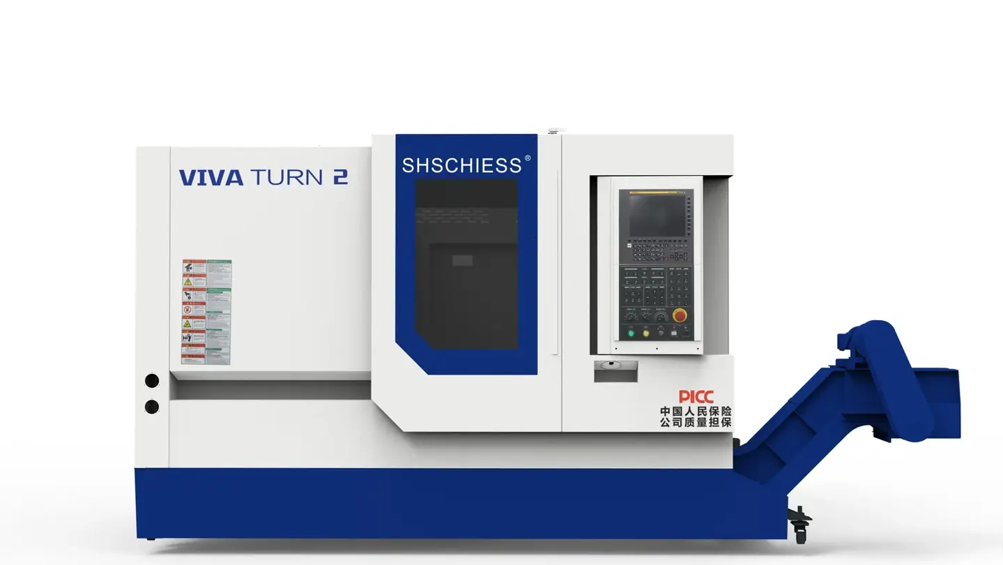
Representative series image. Configuration and enclosure may vary.
CNC TURNING CENTRES
T2/1000
A full-function CNC lathe with GSK control, an eight-station turret and hydraulic tailstock for supported shaft machining.
Configured to order. Final specification, delivery and pricing are confirmed in your quotation.
TECHNICAL PROFILE
The details
that matter.
Reference configuration from manufacturer technical documentation. Options and document editions can differ; agree the exact configuration before ordering.
| Parameter | Specification | Unit |
|---|---|---|
| Swing over bed | Ø560 | mm |
| Maximum cutting length | 1000 | mm |
| Maximum turning diameter | Disc Ø400Shaft Ø350 | mm |
| Swing over cross slide | Ø350 | mm |
| Spindle nose | A2-6 | |
| Spindle bore | Ø65 | mm |
| Bar capacity | Ø50 | mm |
| X rapid traverse | 30 | m/min |
| Z rapid traverse | 30 | m/min |
| X-axis travel | 200 | mm |
| Z-axis travel | 1050 | mm |
| Tailstock travel | 900 | mm |
| Machine weight | 4800 | kg |
| Machine dimensions (L × W × H) | 3570×2000×2200 | mm |
| Spindle speed range | 50–4,500 | rpm |
| Turret | 8 stations |
FROM SPECIFICATION TO PRODUCTION
Let your component
lead the conversation.
Share the workpiece
Send material, dimensions, drawings and your required tolerances.
Define the process
Review workholding, tooling, spindle speed and control requirements.
Confirm the configuration
Agree a technical proposal, acceptance criteria and delivery schedule.
CONFIGURATION IN CONTEXT
Planning with T2/1000.
Start with cutting capacity
Check finished diameter and cutting length together. Swing over the bed describes clearance, while tool position, chuck jaws and the turret can restrict the actual machining envelope.
Choose the workholding route
For bar work, confirm spindle bore, drawtube clearance and feeder compatibility. For long shafts, review tailstock support, centre distance and the effect of slenderness before selecting a bed length.
Specify each operation
List facing, roughing, finishing, boring and threading. Milling or cross-drilling requires a separately confirmed driven-tool and axis configuration; these functions are not implied by a standard turning-centre listing.
T2/1000 or T2/500?
These are published differences between the reference configurations. They help narrow a shortlist; they do not establish interchangeable tooling or identical performance.
| Parameter | T2/1000 | T2/500 |
|---|---|---|
| Maximum cutting length | 1000 mm | 500 mm |
| X-axis travel | 200 mm | 210 mm |
| Z-axis travel | 1050 mm | 560 mm |
| Tailstock travel | 900 mm | 450 mm |
PRACTICAL ANSWERS
T2/1000 FAQ
What is the swing over bed of T2/1000?
T2/1000 lists Ø560 mm for swing over bed in the reference configuration. Confirm this value in the order-specific technical agreement and check tooling and workholding clearance.
What is the maximum cutting length of T2/1000?
T2/1000 lists 1000 mm for maximum cutting length in the reference configuration. Confirm this value in the order-specific technical agreement and check tooling and workholding clearance.
What is the maximum turning diameter of T2/1000?
T2/1000 lists Disc Ø400Shaft Ø350 mm for maximum turning diameter in the reference configuration. Confirm this value in the order-specific technical agreement and check tooling and workholding clearance.
What should I compare with T2/1000?
T2/500 is another model in this machine family. Review the differences above and both specification tables against the same drawing, tooling and installation requirements.
What is the price and delivery time for T2/1000?
This machine is configured to order. Send your controller preference, workpiece details, accessories and delivery destination so the team can confirm a complete quotation and production schedule.
How will T2/1000 be inspected before acceptance?
Agree the supplied configuration, geometric checks, sample machining and measurement method before ordering. Factory pre-acceptance and acceptance after installation should use the agreed technical requirements. See our quality and acceptance guide for the inspection planning process.
YOUR NEXT PRODUCTION CHAPTER
Let’s build what
comes next.
Start with your component, material and production target. We will help define the machine configuration.
Discuss your project